|
Triumph TR7 Rover V8 engine conversion
|
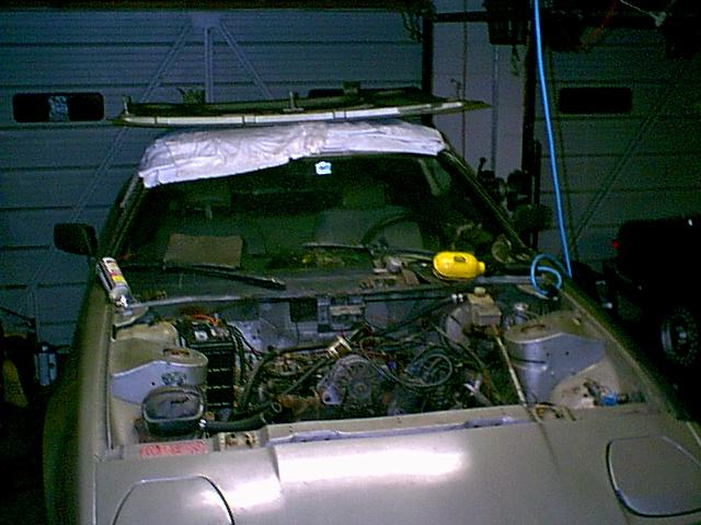
There is something wrong with the Mazda RX-7 engine that someone has fitted to our silver TR7. It has little power and smokes something awful. Besides, it looks silly in that engine compartment which was, after all, designed from the very start (as proven by Kimberly's book) to be fitted with a Rover V8.
For more details see: TR7 V8 Conversion Page |
 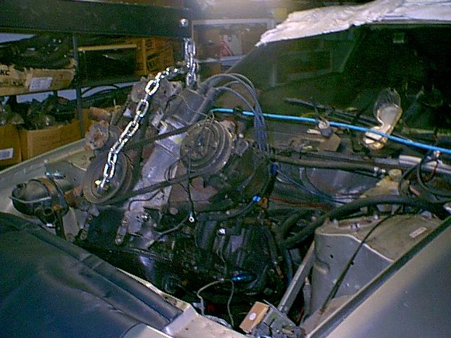 |
We began by removing the bonnet and draining the engine oil, coolant & gear oil. Next we removed the exhaust system and propshaft. We then connected the engine hoist and placed a floor jack under the rear gearbox mount before removing the four nuts that secure it to the body.
Away it goes - back to an RX-7 engine bay where it belongs! |
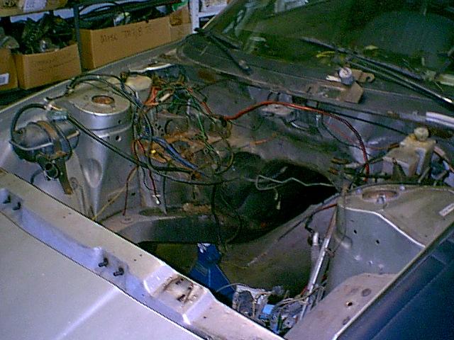  |
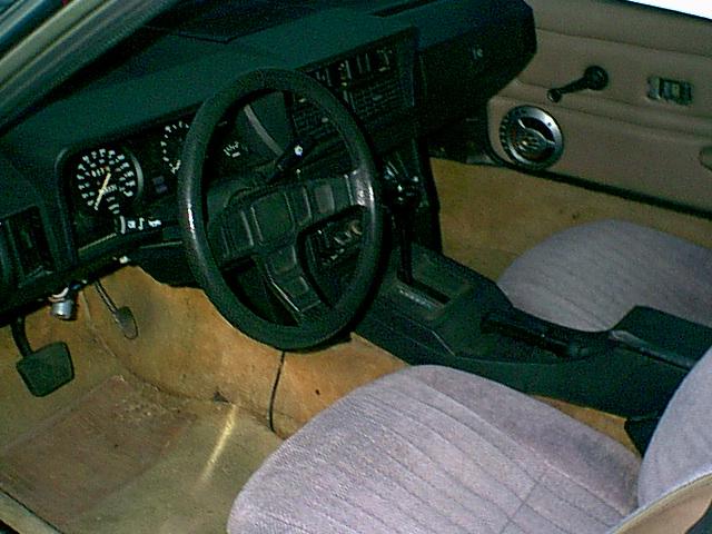
The RX-7 lump is gone. This is fairly typical of a TR7 engine compartment once the engine & gearbox are removed. Depending upon the actions of previous owners, one will encounter a wiring mess equal to, or perhaps worse than shown here. Attention to detail & care taken with wiring is something that will make the difference between a conversion that has a professional 'factory' look and one that looks shabby. |
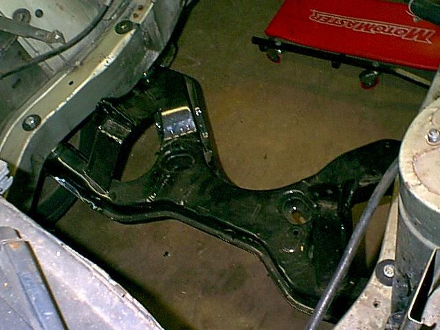 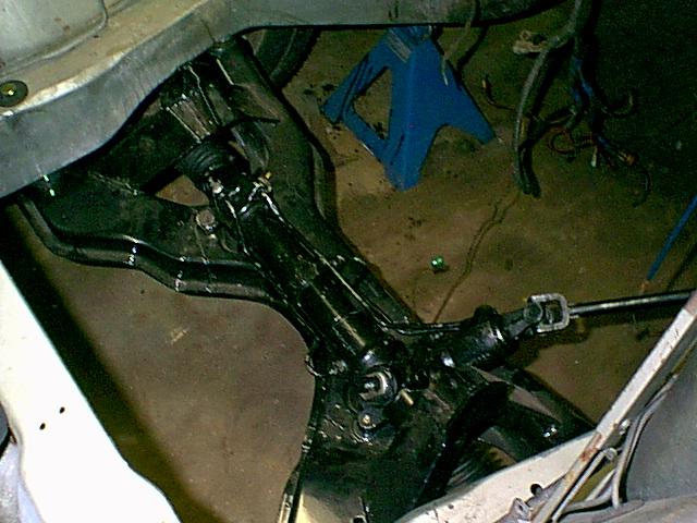 |
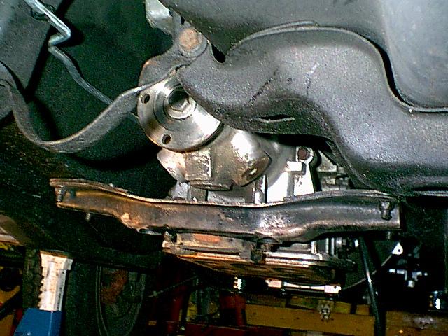
The V8 subframe is in. We decided to go with the modified TR7 subframe for this project and it is a very nicely made product. Some would say that this marks the official turning point of going from a TR7 to a TR8. We were also fortunate to find a genuine TR8 power steering rack. We are working on an alternative power steering setup for future projects since genuine TR8 power racks are rare. The rack needs to be installed before the engine otherwise it will be necessary to remove the subframe! |
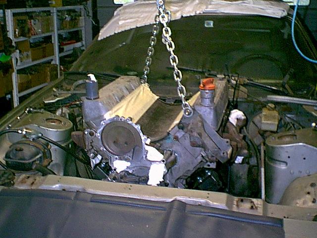  |
Lowering the engine into place. For ease of installation it is desirable to remove many of the front engine components. It is also a good idea to remove the bonnet latch. |
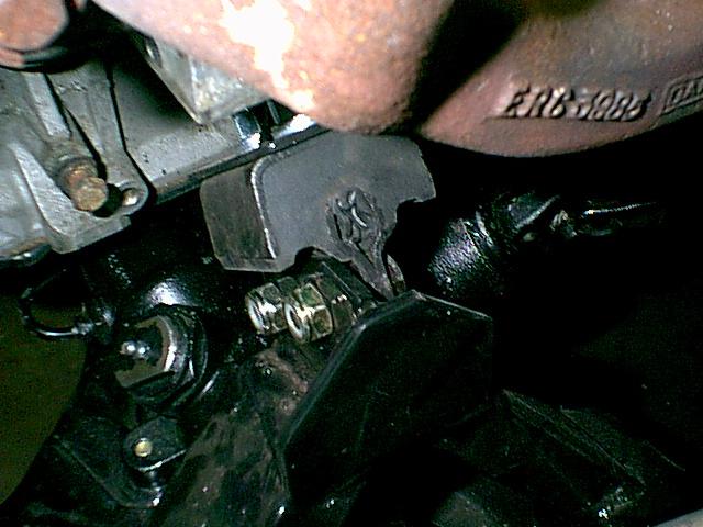  |
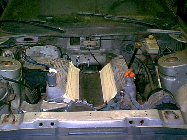
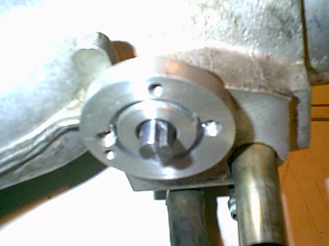
The photo on the left shows how the engine mount & bolts should be oriented. The manual does not explain it clearly in the text, although there is an illustration buried away in there!
At this point we decided to offer up the alternator and a/c compressor bracket to ascertain what kind of clearance there would be. The alternator just clears the bonnet if one removes the guard that is fitted on later engines. |
 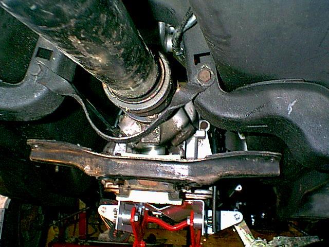 |
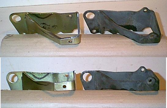
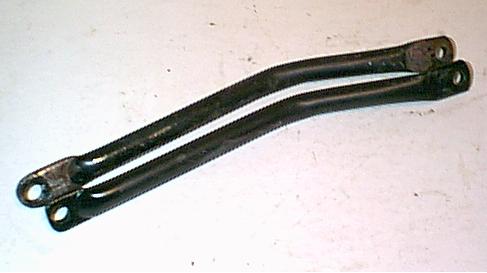
It will be necessary to move the rear engine (transmission) mount about one inch farther back, which requires drilling new holes for the two stud plates on either side of the gearbox tunnel. |
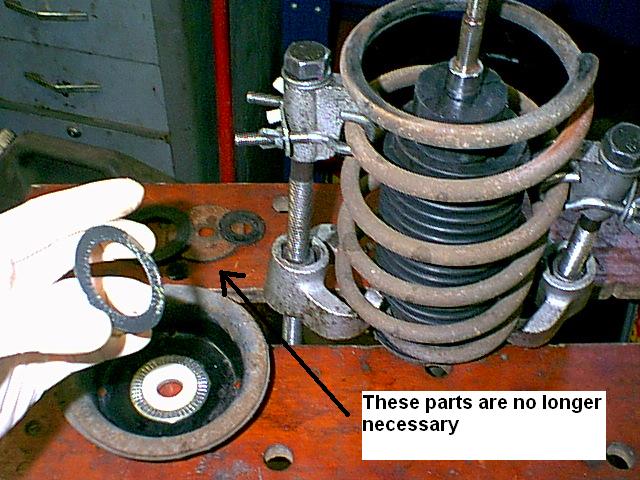 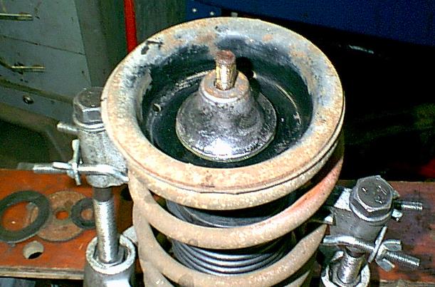 |
At this stage we took the opportunity to fit an upper strut bearing kit, which updates the pathetic bushing fitted from the factory. Every other Macpherson strut car in the world uses some form of anti-friction bearing in this area, and this kit should be regarded as an unofficial 'recall' for all TR7's and TR8's. We believe it is especially important on TR8's to avoid putting undue stress on the steering rack seals.
The dampers (shocks) on this car seemed OK, so all that remained was to fit new dust boots, bump stops, lower ball joints and inner control arm bushings. We now have the ability to offer these bushings installed in lower control arms on an exchange basis, along with a limited supply of NOS units. |
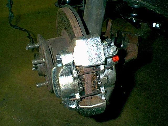 |
It is essential to uprate the brakes when installing a Rover V8 in a stock TR7. The discs are stock TR8 (yes they're in rather poor shape but do for a mockup set). The calipers appear to be from the SD1. Genuine TR8 calipers are rare. We had to remove a small amount of material from the rear dust shield at the top of the caliper and around the inner radius of the caliper to make the inner brake pad fit. The outer pad is a very tight fit and required some gentle persuasion from a "BFH" to get it in, but uneven pad wear is more or less a fact of life on these cars anyway! Some rebending of the line will likely be required as well as adding washers under the outer section bolts to ensure enough disc clearance. |
 |
We decided to use the remote power steering reservoir as fitted to Range Rovers. We may also have to lower the alternator by mounting it deeper in the main bracket to provide enough bonnet clearance. |
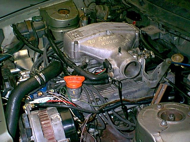  |
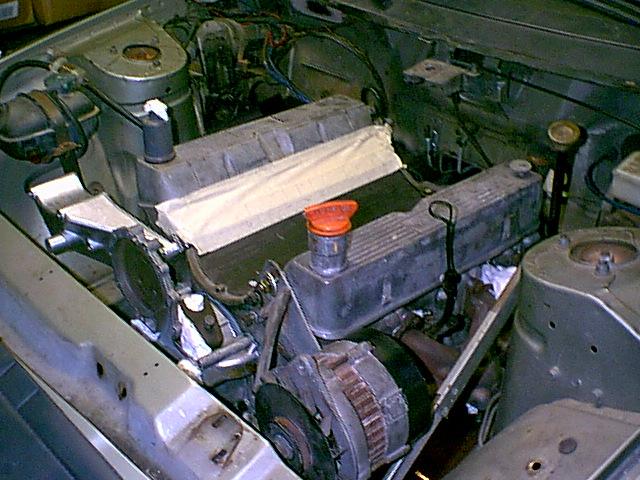
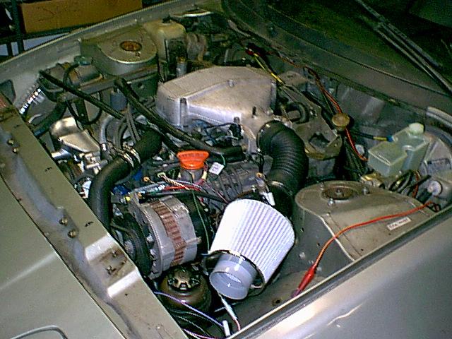
The engine is now running! The only major issue remaining to be solved concerns the throttle position sensor which is not compatible with the GM electronics that we are using. It appears that the Rover sensor is a switch, whereas the GM ECM is looking for a progressive change in voltage from approx 0.5 to 4.5 volts as the throttle is opened. |
 |
We had to remove the bonnet in order to observe the timing marks without parallax error. We're also not thrilled with the upper rad hose routing. |
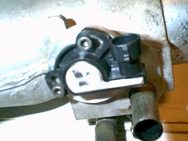  |
It was necessary to have some parts machined to mount the later style GM rotary TPS. We can offer this as a complete bolt on kit - no modification to the plenum is required. |
  |
We decided to move the bonnet support to the passenger side of the engine compartment to avoid interference with the air cleaner. The strut tower is drilled to accept the telescoping support on either side! The bonnet will need to be drilled and fitted with the appropriate captive nut inserts. |
  |
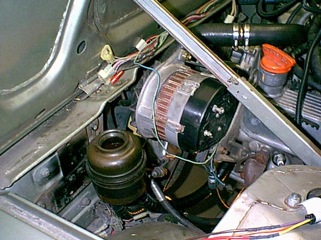
When we installed the bonnet it was discovered that the alternator was indeed too high. We lowered it by mounting it deeper into the bracket. This required drilling new holes and grinding off the material surrounding the old ones. It was also necessary to shorten the support rod. |
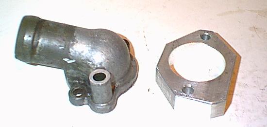 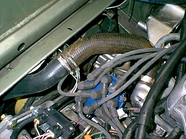 |
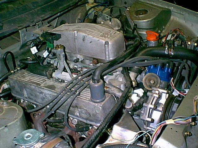
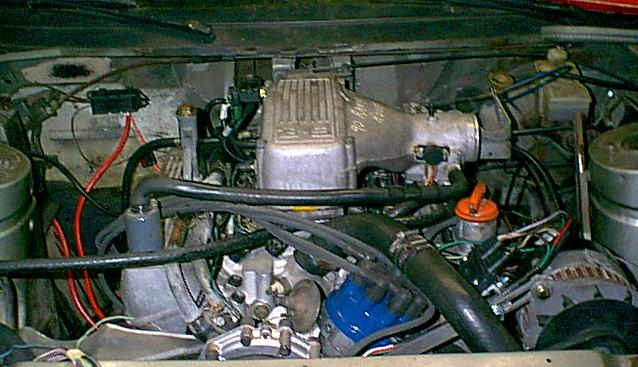
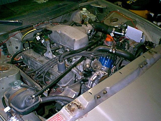
The upper radiator hose was routed perilously close to the alternator belt and also prevented removal of the distributor cap. The solution was borrowed from the Jaguar XK engine. The thermostat housing shown would not bolt up to the intake manifold because of the outlet angle. Therefore a spacer was manufactured to solve the problem. The radiator hose is a combination of an upper hose for an a/c car and one from a non a/c car! The latter has a sharper bend at the thermostat housing end. If enough of these Range Rover engined cars get built we will have a batch of custom hoses produced. |
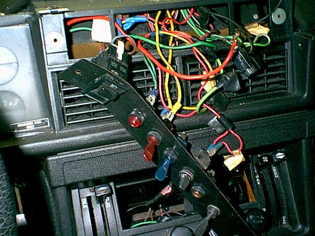  |
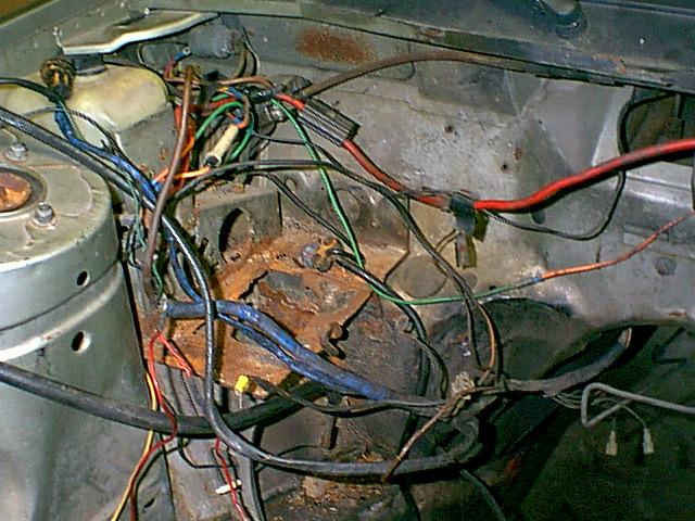
Viewers of the television show "Blue Collar TV" will probably know of their feature 'redneck yard of the week': Here at Wedgeparts we are going to have own version: 'redneck repair job' The dash wiring in the left photo certainly qualifies. We did not even begin to sort this mess out - it was promptly ripped out and the original switch panel restored. There were issues with the turn signals and dash lights not working, and both problems were traced back to the fusebox. When checking wedge fuses be sure to verify that one has power on both sides as well as both ends of the fuse! This is important because the ( . ) that retain the fuse frequently feed two separate circuits. We have now found a source for the fusebox terminals and are investigating the possibility of getting the plastic housings reproduced. |
| smog check report (pdf file) |
Even though we do not have emissions testing in our area (yet), I decided that it would be interesting to take this car through the inspection station in Nashville to see how it would perform.
The car passed with very respectable readings of 64 ppm for hydrocarbons (HC) and 0.54% for carbon monoxide (CO). The limits are 300 ppm for HC and 3% for CO, so these results are quite impressive considering no catalytic converters are installed. Carbon dioxide (CO2) was 7.21% (no limit was specified).
Despite having a giant inspection mirror, the ground clearance is such that the tester must have just assumed that catalytic converters were present! |
Wedgeparts would like to thank Chris and the team at PTL Fabricators of Clarksville (formerly North Tennessee Tool & Die)
for their assistance without which this project would not have been possible. |
|
|